Introduction
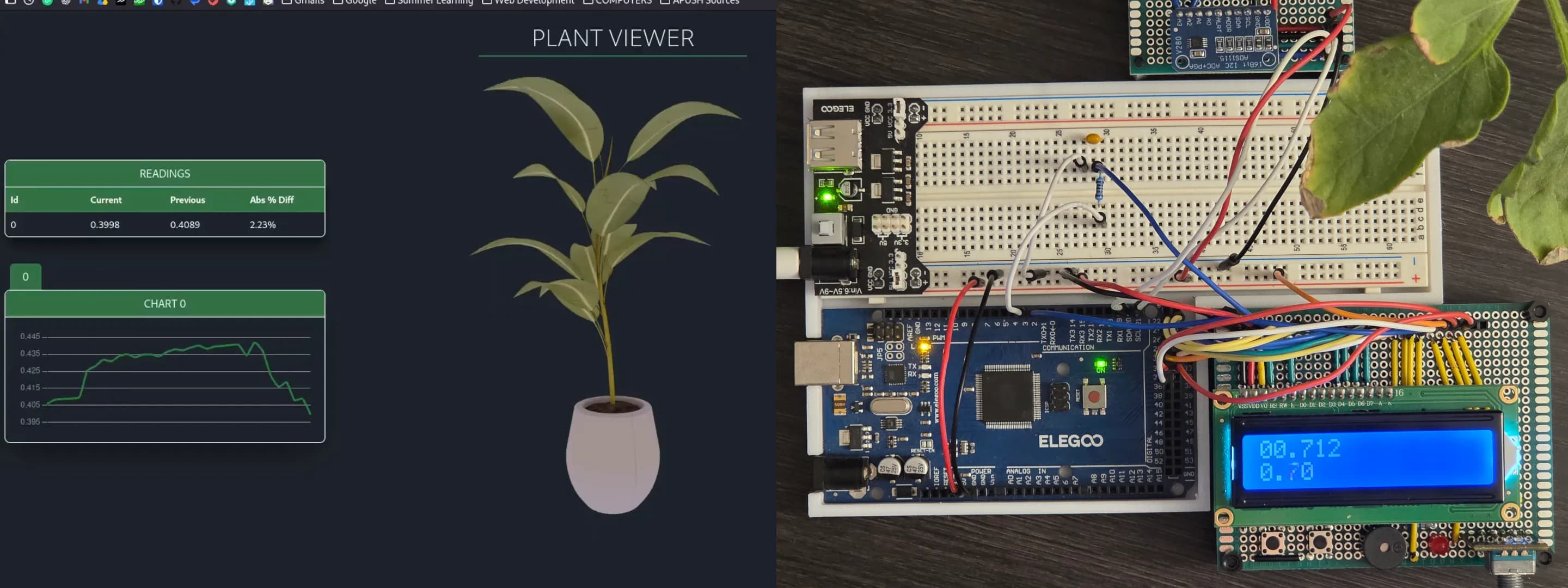
Across two summers I worked with a post-graduate at NC State who was researching a plant sensor material. His focus was primarily material science, however, my involvement was main revolved around the electronics and software. The goal of the project was to develop a "digital twin interface" for viewing plant stimuli. This involved building the electronics and programming the backend/frontend.
Contents
The project has been broken into these main sections:
The Design
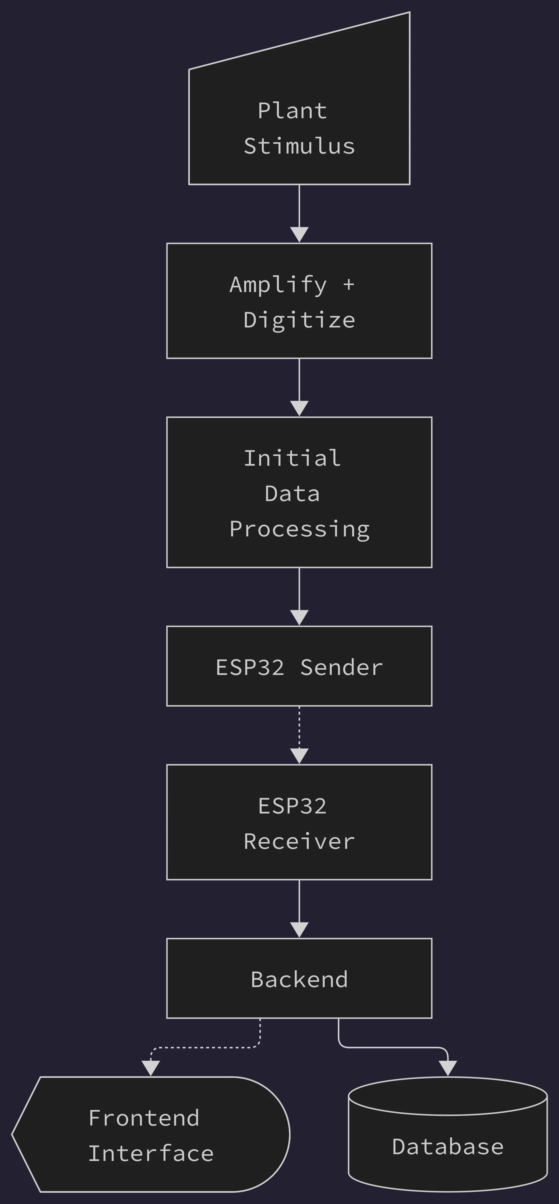
The overall design of the project can be broken into 8 parts. These eight parts will be grouped together and explained in more depth, but this will give a general overview of purpose:
1. Plant Stimulus - Stimuli, mainly touching the plant, are detected through two electrodes on the stem of the plant. The exact material and design of the electrodes was the research's focus.
2. Amplify + Digitize - An amplifier and an Analog-to-Digital Converter are used together to amplify the tiny milivolt signals from the plant into digital numeric values.
3. Initial Data Processing - An arduino receives the data and outputs a JSON string over Serial (UART)
4. ESP32 Sender - An ESP32 sends the JSON strings wireless over ESP-NOW to a receier ESP32.
5. ESP32 Receiver - An ESP32 receives the data and sends it to the backend over Serial
6. Backend - A backend running on any PC serves the data to the frontend and saves it to a database
7a. Frontend Interface - The "digital twin" interface that shows plant stimuli on a web UI.
7b. Database - The database stores the most recent data, as well as persistent values like thresholds.
The Electronics
Basic Design
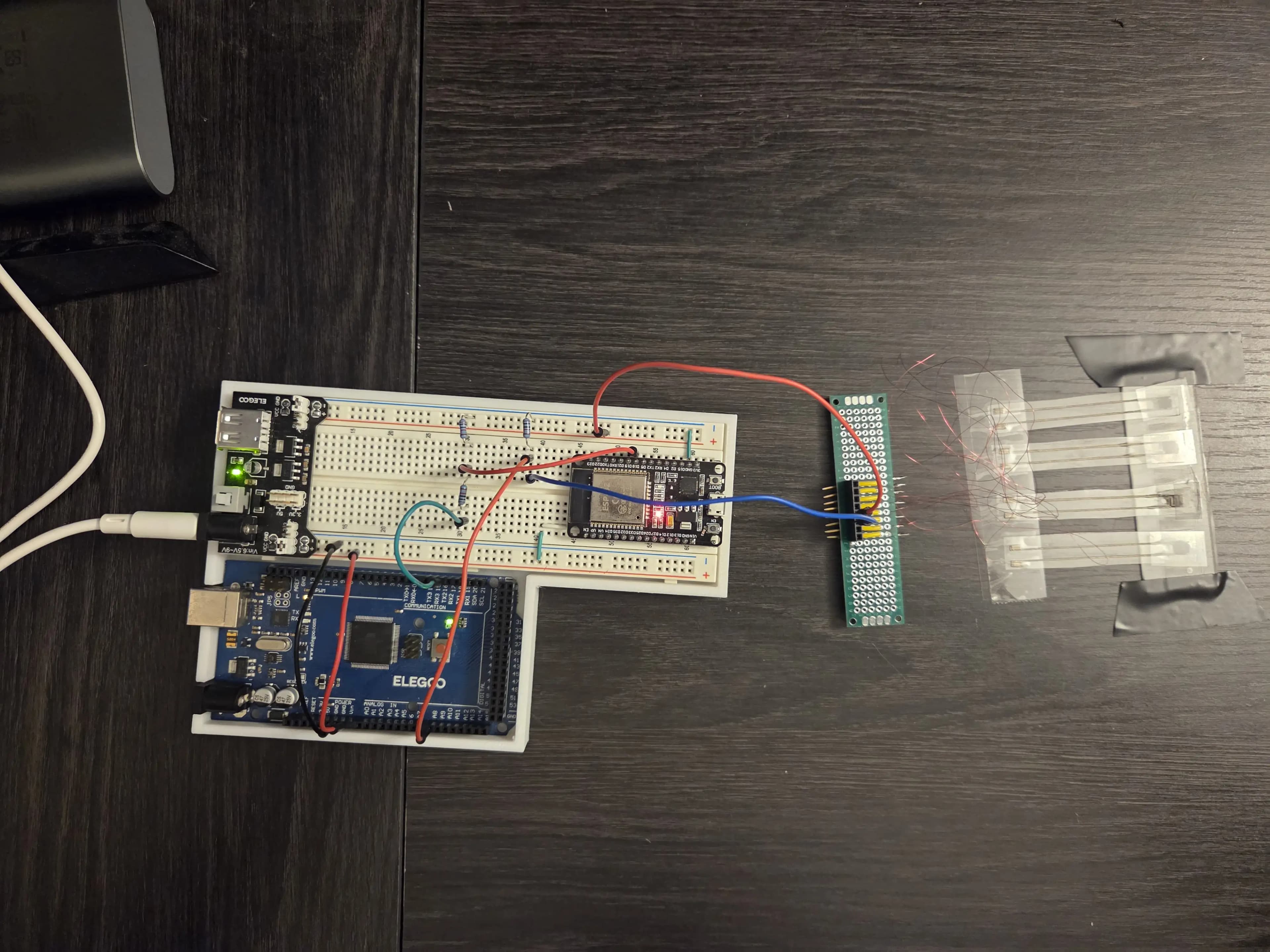
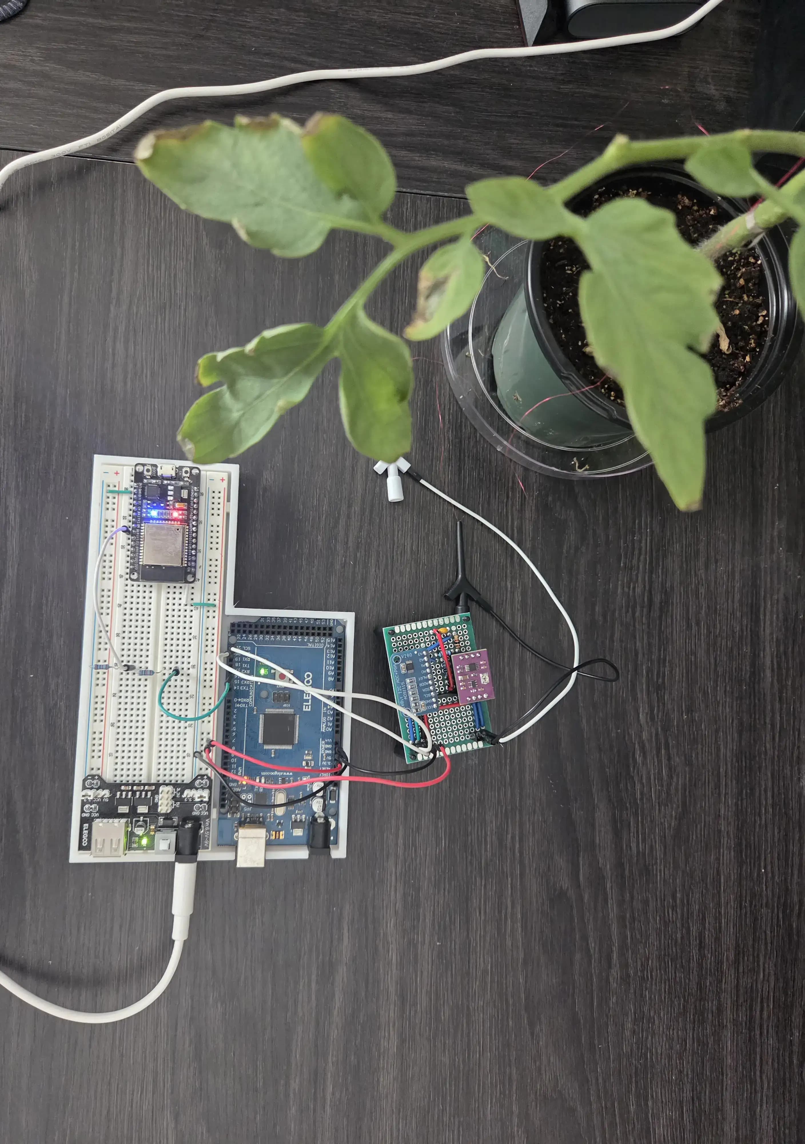
The electronics involve reading the plant signal and sending them to be processed by the backend. Initially, I was given force-sensitive resistors to test with. Because they didn't need amplification, I used an Arduino's built in ADC. The Arduino then sends the formatted data to the sender ESP32 over UART. There are two ESP32s that communicate over an ESP-NOW network to send the data wirelessly.
Amplifier Circuit
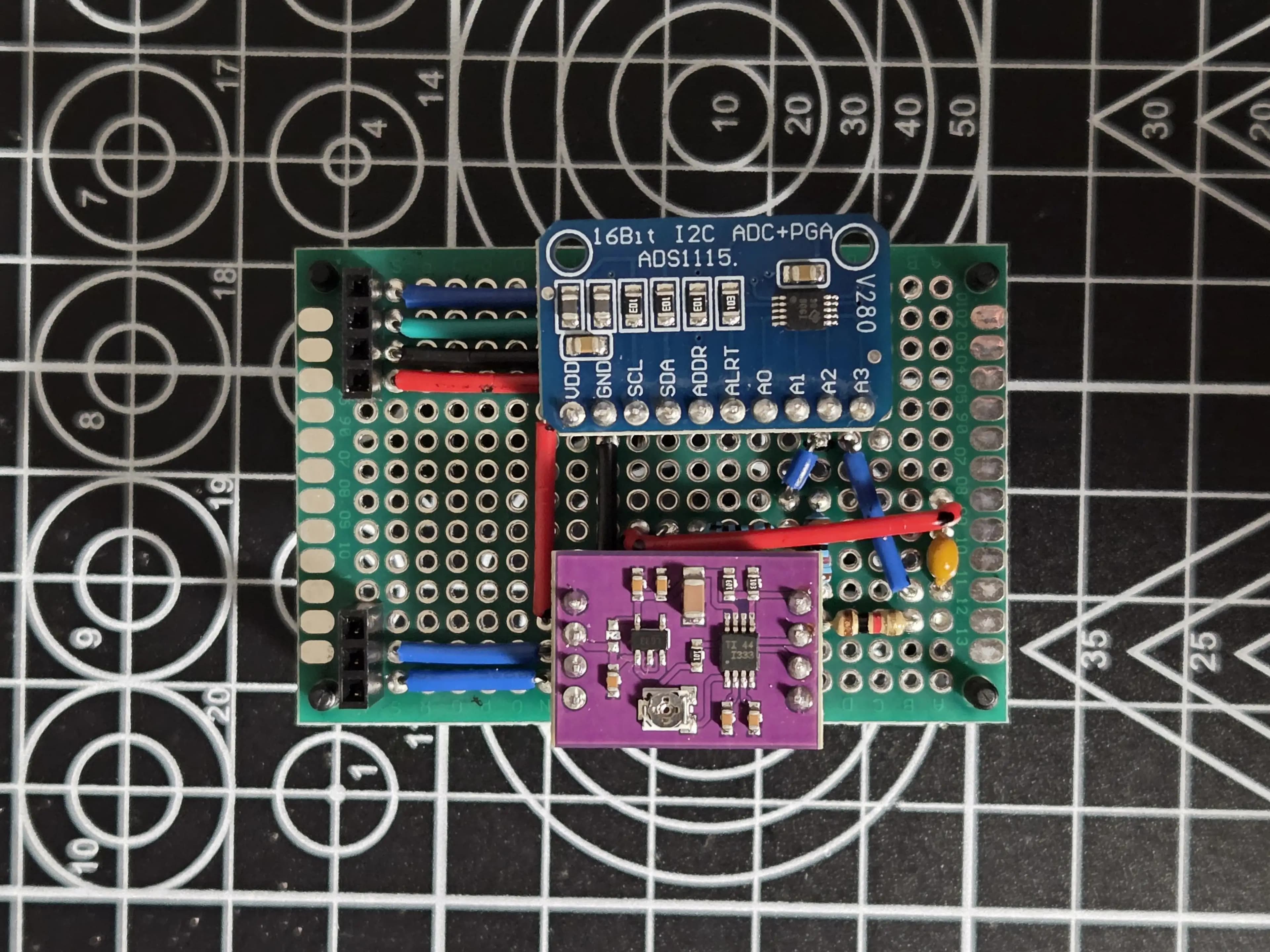
After that circuit worked well enough, I was given a plant to test real stimuli. An issue I ran into was that all my readings were 0V. The Arduino couldn't read the tiny voltages and the high impedance plant tissue. To fix this, I used a combination of an INA333 and ADS1115. The INA333 is a high impedance input that can amplify the small voltages into usable voltages. Then, the ADS1115 acts as the Arduino's ADC with a higher resolution. Instead of using the Arduino's analog pins, I just connected the I2C pins to the ADS1115.
The Backend
Words
The Frontend
Words
Other Additions
Words